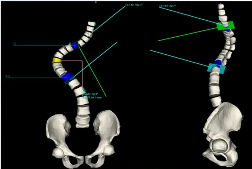
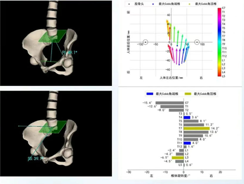
1. Full Spine Measurements
On an AP view X-ray, identify the upper and lower end vertebrae. Draw lines along their respective endplates and measure the intersecting angle or perpendiculars, i.e., Cobb’s angle.
Vertebral Rotation Angle (Nash-Moe Method):
Graded based on pedicle displacement on AP view X-rays.
Time: 2–3 minutes per vertebra.
Axial CT Rotation Measurements:
Assess pedicle–rib angle or vertebral–spinous process angle.
Time: 5–10 minutes for full spine (requires multi-slice reconstruction).
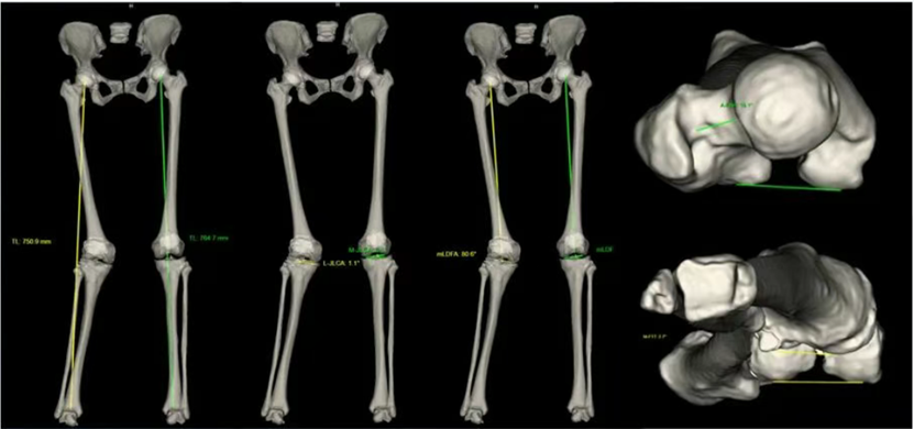
2.Full Lower Limb Measurements
Functional Lower Limb Length:
Distance from femoral head center to ankle joint center on erect position radiology.
Time: 1–2 minutes (Bilateral comparison)
Mechanical Axis Deviation (MAD):
Vertical distance from the knee joint center to the line connecting the femoral head center and ankle joint center.
Time: 2–3 minutes (Magnification calibration required )
Hip–Knee–Ankle Angle (HKA):
Angle between mechanical axes of femur and tibia.
Time: 3–4 minutes (Precise joint center identification required)
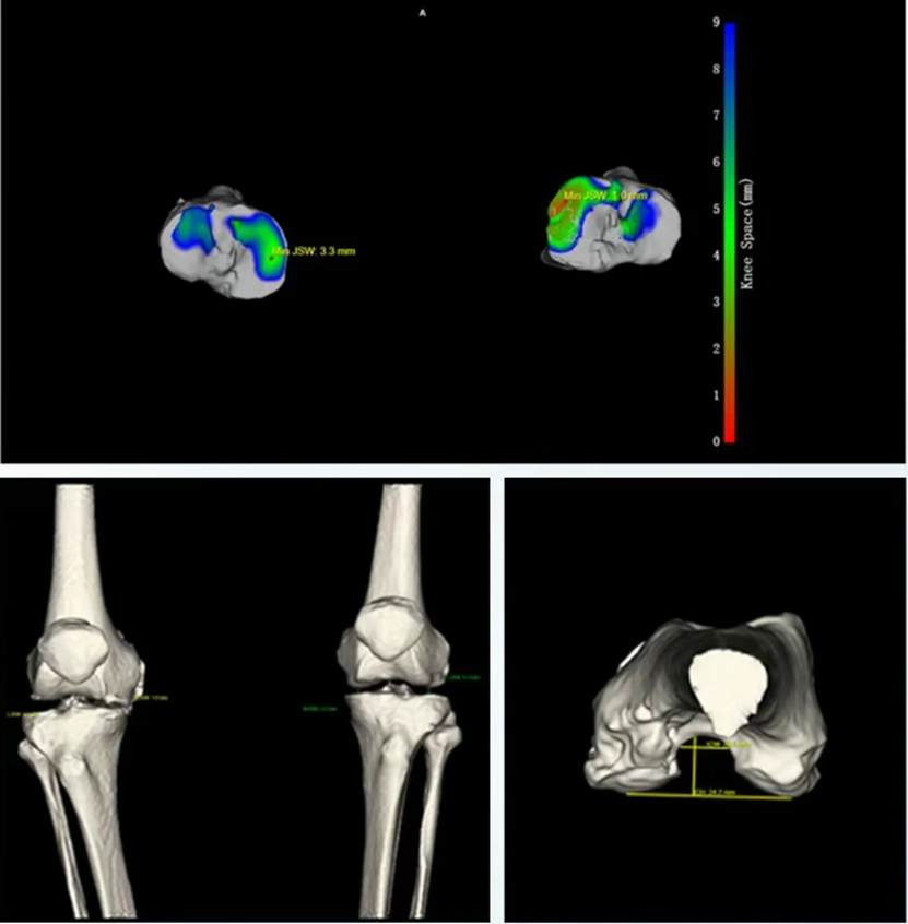
3.Knee Joint Measurements
Femorotibial Angle (FTA):
To evaluate Genu Varum (bow legs or knock knees).
On erect position radiology, draw the femoral mechanical axis (from the center of the femoral head to the knee joint) and the tibial mechanical axis (from the center of the knee joint to the ankle joint). Measure the lateral angle between these two axes.
Femoral Torsion Angle:
CT-based angle between femoral neck axis and the posterior tangent line of the femoral condyle (transverse position + 3D reconstruction required).
Time: 5–8 minutes per side
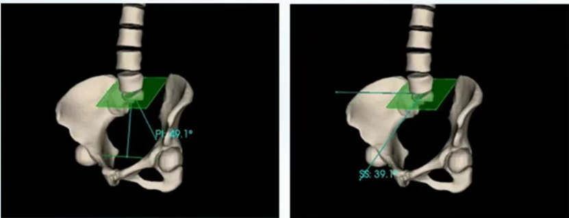
4.Hip Joint Measurements
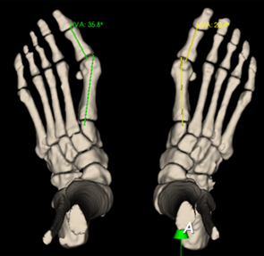
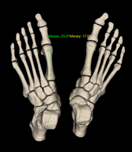
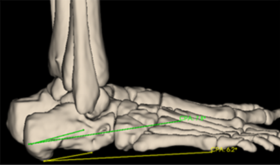
5.Foot & Ankle Measurements
Automatic Measurement System: Precision Meets Efficiency
- World’s first system supporting automated full spine, lower limb, and single part measurements
- Covers nearly 200 measurement parameters
- Generates structured reports in just 15 seconds
- Provides Median sagittal section and torsional data of joints under weight-bearing conditions
- Uses independent coordinate systems for each limb to reflect true deformities
- Supports 3D printing of scanned anatomical models for use in brace design, surgical planning, and clinical education
1.Full Spine Automatic Measurement
2.Full Lower Limb Automatic Measurement
3.Knee Joint Automatic Measurement
Supports MPR-based 3D reconstruction and AI evaluation of parameters such as medial/lateral joint space width, JLCA, joint gap heat map, intercondylar notch width/height, and notch width index.
4.Hip Joint Automatic Measurement
5.Foot & Ankle Automatic Measurement
Supports Pitch angle, Meary angle, Böhler’s angle, Preiser’s angle, Langré’s angle, etc., with 3D-printable models for clinical use.
WR-3D Automatic Measurement: Powering the Future of Orthopedics
Consistent: Eliminates operator-dependent variability
Carmen et al. (2017).Spine Deformity. DOl 10.1016/j.jspd.2016.12.001
Zhang et al.(2019).Eur Spine J. DOl 10.1007/s00586-019-05924-3.
Wu et al. (2020).J Orthop Res. DOl 10.1002/jor.24567.
Nash & Moe (1969).JBJS.PMID 5783856.
Stokes et al. (2006).Spine. DOl 10.1097/01.brs.0000215429.97572.aa.
Liu et al.(2021).Nat Commun. DOl 10.1038/s41467-021-22118-y.
Kuklo et al.(2005).Spine.DOl 10.1097/01.brs.0000155405.00881.9a
Paley D.Principles of Deformity Correction (Springer, 2002).
Brouwer RW,et al.Osteoarthritis Cartilage 2007;15(6):644-651.
Botser lB,et al. CORR 2011;469(12):3432-3440.
Zhang J, et al. Med lmage Anal 2021;73:102191
Vialle et al.(2005), Spine, PMD 15770185
Legaye et al.(1998),Eur Spine J, DOl 10.1007/s005860050038
Seltzer SE,et al.(1984). Foot Ankle. PMlD 6745901.
Saltzman CL, el-Khoury GY(1995).Foot Ankle. PMD 7550940.