
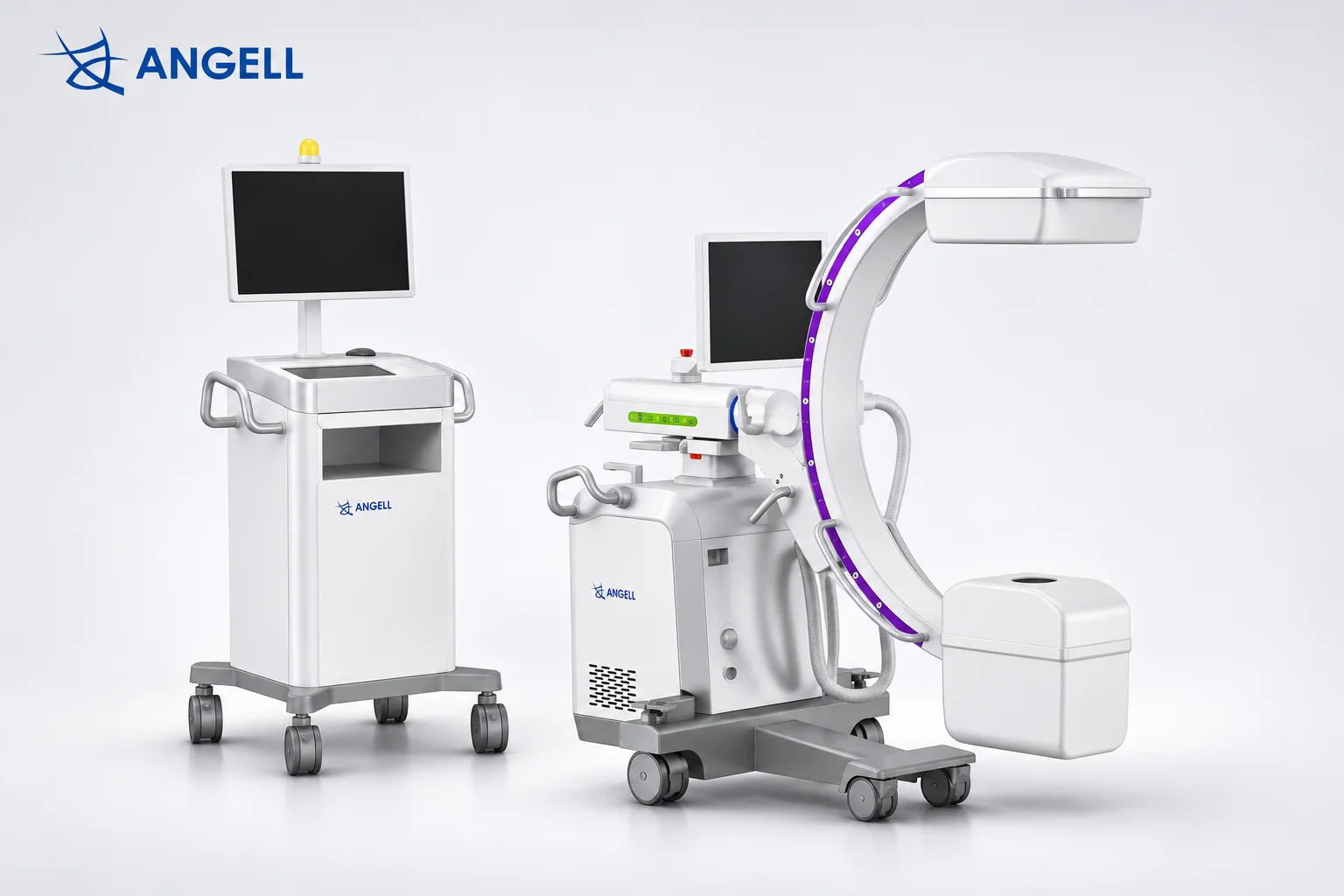
The main C-arm parts include the X-ray tube, high-voltage generator, collimator, filters, detector, C-shaped gantry, mobile base, control panel, image processor, and monitor. During fluoroscopy, the system produces live X-ray images that clinicians can view on a monitor.
Our HUA II Series uses a dynamic flat-panel detector at one end of its C-shaped imaging assembly, opposite the X-ray source. When the arm is repositioned, the source and detector move together, keeping the receptor in the X-ray path.
Main C-Arm Parts and Their Functions
| C-arm part | Primary Function |
|---|---|
| X-ray tube | Generates the X-rays used to produce images. |
| High-voltage generator | Supplies and regulates the electrical power needed for X-ray exposure. |
| Collimator | Limits the X-ray beam to the area being examined. |
| Filters | Removes some low-energy X-rays before they reach the patient. |
| FPD or image intensifier | Captures transmitted X-rays to form images. |
| C-shaped gantry | Holds the X-ray tube and detector in alignment as the viewing angle changes. |
| Mobile base and brakes | Allows the system to be moved and secured in position. |
| Control panel | Allows operators to select imaging settings and initiate exposures. |
| Image processor | Processes acquired detector data for viewing and review. |
| Monitor | Displays X-ray images for the clinical team. |
Inside the X-Ray Source: Tube and Generator Functions
The X-ray tube produces X-rays, while the high-voltage generator supplies and controls the electrical power needed for exposure. Inside the tube, electrons strike a metal target to produce X-rays. The generator regulates tube voltage, current, and exposure timing, determining the electrical conditions under which the tube operates.
In our ALC280 Series, generator output and tube heat capacity serve different purposes. The generator must deliver enough power for each exposure, while the tube manages the heat produced during repeated fluoroscopy pulses. We consider both electrical output and thermal capacity because adequate generator power alone does not determine how long repeated imaging can be sustained.
Collimators and Filters: Controlling the X-Ray Beam
Collimators control the area exposed to X-rays, while filters remove some low-energy X-rays before they reach the patient. The collimator uses adjustable shutters to shape the beam, and the filter changes the radiation passing through the selected field.
During a C-arm examination, such as checking the position of a fixation screw, the collimator narrows the beam to the screw and surrounding bone that need to be visible. This limits exposure outside the area of interest and can reduce scatter reaching the detector, as discussed in the IAEA’s guidance on fluoroscopy. At the same time, filtration reduces low-energy X-rays that would otherwise be absorbed by the patient’s tissues with little benefit to the image.
Flat Panel Detectors vs. Image Intensifiers: Key Differences in Image Capture
Flat-panel detectors (FPDs) capture digital X-ray images through an electronic pixel array, while image intensifiers use an electron-optical system and a camera. The two technologies also differ in image field shape, geometric distortion, and the physical size of the receiving assembly.
Inside an image intensifier, incoming X-rays are converted into light and then electrons. The electrons are accelerated and focused to form a brighter visible image, which a camera records. An indirect-conversion FPD follows a different path: X-rays are converted into light, then into electrical signals that the detector’s pixels read as digital image data.
These differences are also visible in the resulting images and equipment design. Traditional image intensifiers generally produce a circular image field and may show curved lines near the image edges due to pincushion distortion. FPDs use a rectangular pixel array and avoid this characteristic distortion. Their thinner housing can also provide more clearance near the patient when the C-arm is positioned for lateral imaging.
Our HUA II Series uses a dynamic flat-panel detector for both fluoroscopic image sequences and still-image capture. Clinicians can observe movement through successive frames during fluoroscopy and retain selected images for later review. These two imaging functions are supported by the detector’s digital acquisition capabilities.
How the C-Arm Gantry Positions the X-Ray Tube and Detector
The C-arm gantry positions the X-ray tube and detector by holding them opposite each other on a C-shaped frame. As the arm rotates or tilts, both components move together and remain aligned, allowing X-ray images to be captured from different angles.
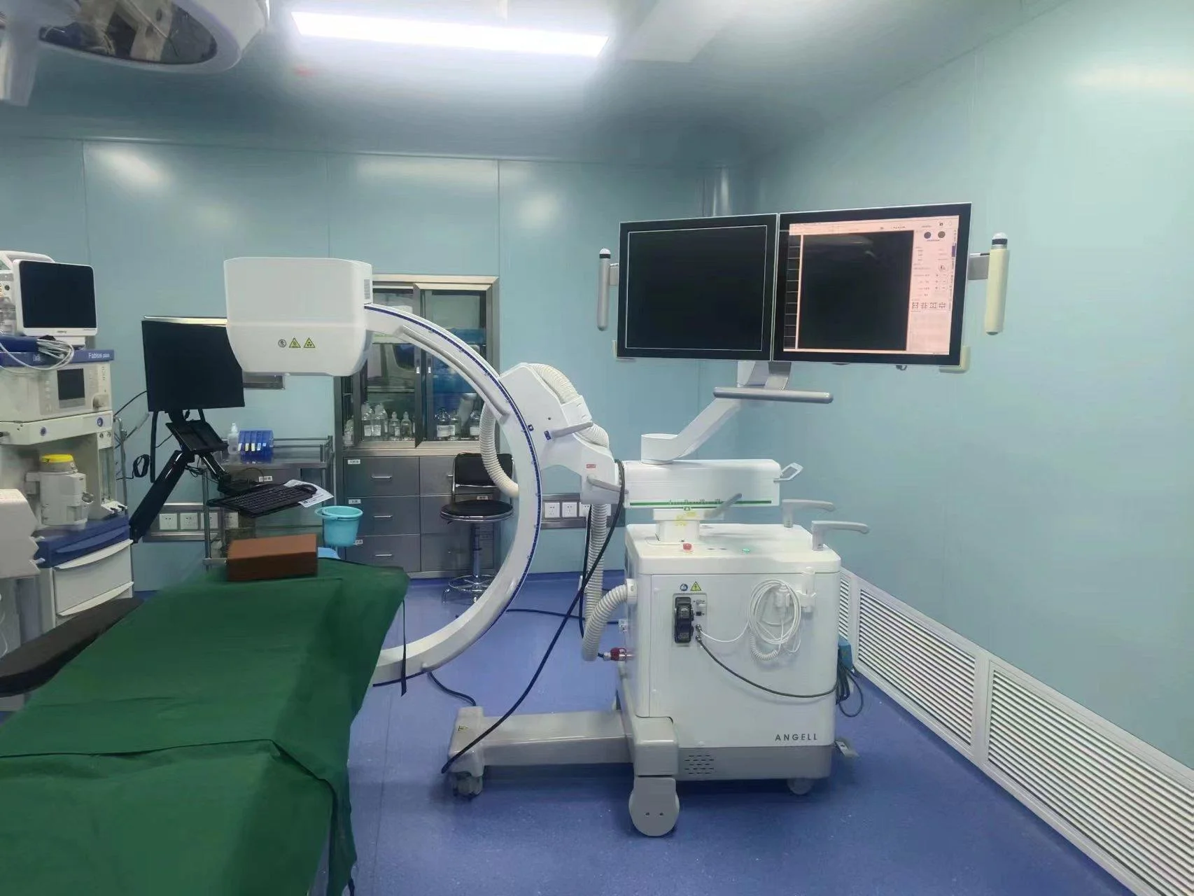
On our ALC280 Series, the mobile base allows operators to move the system beside the operating table, while the brakes secure the chassis in position. For a lateral view, the gantry angle and height can then be adjusted to position the X-ray tube and detector around the patient. Both components remain aligned during these movements, and mechanical locks hold the selected arm position steady for exposure.
What Do the C-Arm Control Panel, Image Processor, and Monitor Do?
The control panel manages exposure settings and imaging commands, the image processor prepares detector data for viewing, and the monitor displays the resulting X-ray images. In our HUA II Series, APR provides preset exposure programs, while ABS and IDC support brightness and exposure regulation during fluoroscopy. The workstation processes the acquired images and makes them available for review and export.
Image display also depends on where the monitor is positioned. HUA II’s integrated configuration uses a three-axis articulated monitor arm that allows operators to adjust the screen angle and reduce obstruction from the C-shaped gantry. For procedures requiring a separate viewing position, the split configuration provides an independent display station.
How the Main C-Arm Components Work Together
The main C-arm components work together by coordinating X-ray exposure, image acquisition, and display. The gantry keeps the X-ray tube and detector aligned, while the control system manages exposure. The detector captures the transmitted X-ray information, and the workstation processes and displays the acquired images. Each updated view provides visual feedback during the procedure.
During percutaneous kyphoplasty (PKP), clear visualization of the vertebral pedicle helps the clinical team assess the instrument path and position. In our HUA II Series, the gantry establishes the required viewing angle, while the collimator limits the X-ray beam to the area being examined. The generator powers the X-ray tube, and the dynamic flat-panel detector captures the transmitted X-ray information. The workstation displays the resulting images, allowing the team to check instrument placement before making further adjustments.
When clinicians capture an image to check instrument position, the time required for that image to appear on the monitor also matters. In our C-arm engineering reviews, we measure the interval between activating exposure and displaying the resulting image. This measurement covers exposure control, image acquisition, processing, and display, helping us evaluate the system’s overall response rather than relying on detector specifications alone.
Frequently Asked Questions About C-Arm Parts
1. Which C-arm components require calibration or periodic performance checks?
Flat-panel detectors may require image calibration. X-ray tubes and generators undergo output consistency checks, while mechanical positioning systems require alignment checks. Dose indicators also need periodic accuracy testing to maintain reliable performance.
2. Are C-arm parts interchangeable between different models?
Most C-arm parts are model-specific and cannot be freely interchanged. X-ray tubes, detectors, generators, and control boards must be compatible with the system’s electrical connections, mounting structures, and software. Similar specifications do not guarantee compatibility.
3. Can a detector upgrade alone ensure a lower radiation dose?
A detector upgrade alone cannot guarantee a lower radiation dose. A more sensitive detector may support lower exposure while maintaining usable image quality, but patient dose also depends on the system’s exposure settings and automatic exposure controls.
Conclusion
When evaluating C-arm parts, we look beyond individual specifications to how the complete system performs during a procedure. Positioning space, exposure response, and image viewing arrangements all influence how the equipment fits into the operating room. These practical considerations guide our approach to C-arm design and help identify which features matter for different clinical applications.
Our HUA II Series mobile C-arm combines dynamic flat-panel imaging, integrated exposure controls, and flexible workstation configurations. If you’re exploring C-arm solutions for your facility or distribution business, our technical team can help you understand how these components and design features align with your imaging requirements.