
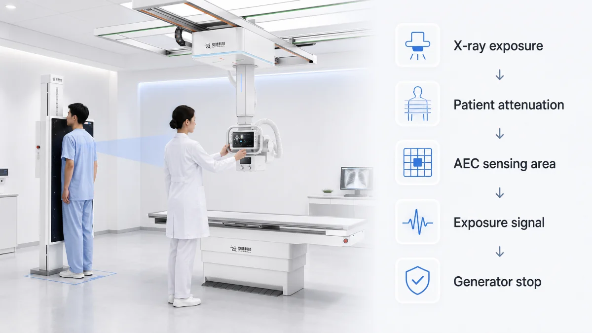
Automatic exposure control (AEC) mode is designed to help a digital radiography system achieve appropriate detector exposure when patient thickness, anatomy, and X-ray attenuation vary from one examination to another. In a DR environment, this matters because image brightness after processing does not always reflect whether the detector received the intended exposure.
AEC is not simply an “auto” button. It is an exposure-termination function that measures transmitted radiation and stops the exposure once the detector-side signal reaches a preset target. When it is correctly configured and used with proper positioning, chamber selection, collimation, calibration, and exposure index review, AEC can support more consistent image quality and more controlled radiography processes.
Its clinical value is clearest in routine examinations where patient attenuation varies, and the anatomy can still be positioned reliably over the selected sensing field, such as chest, abdomen, pelvis, and spine imaging
How Does AEC Work in DR Systems?
AEC mode works by monitoring the radiation that passes through the patient and reaches an AEC chamber or detector-side sensing area. The system converts that transmitted radiation into an electrical signal. As exposure continues, the signal accumulates. When it reaches the preset threshold for the target detector exposure, the generator stops the exposure.
A typical AEC workflow includes five steps:
In many general radiography systems, AEC primarily determines when the exposure ends, thereby affecting exposure time and final mAs. The exact technique factors controlled by AEC vary by system and modality; mammography AEC may involve a broader combination of exposure parameters.
Radiation Attenuation and AEC Response
The same AEC setting can behave differently in lung, abdomen, spine, or pediatric imaging because each body region attenuates X-rays differently.
Lung tissue has relatively low attenuation so that more photons can reach the sensing chamber within a shorter time. Dense soft tissue, bone, body habitus, contrast material, or metal hardware can reduce the number of photons reaching the chamber. When fewer photons reach the sensing area, the accumulated signal rises more slowly, and the system may extend exposure time to reach the target detector exposure.
This is the reason chamber selection matters. If a PA chest exposure uses a chamber positioned under the mediastinum instead of the lung field, the system may receive a weaker signal and continue exposure longer than intended. If the chamber is partly under open air, the opposite can happen: the signal may rise too quickly, terminating the exposure before the anatomy receives adequate detector exposure.
A useful way to think about AEC is a chamber response curve. The detector-side signal rises during exposure. Different anatomy changes the slope of that signal. A steeper curve reaches the threshold faster; a flatter curve reaches it later. Proper positioning and chamber selection help make that curve represent the diagnostic region rather than the wrong anatomy.
Main Components of an AEC System
A conventional AEC implementation typically involves a radiation-sensing element, control electronics, communication with the X-ray generator, and calibration to the image receptor and clinical protocol.
The sensing unit may be an ionization chamber, a solid-state sensor, or another detector-response feedback design depending on the equipment. In many general radiography systems, technologists can select different sensing fields, such as left, center, or right chambers.
Detector integration is especially important in digital radiography. Stable AEC performance requires alignment between detector response, image processing behavior, exposure index feedback, and deviation index review. In routine quality management, imaging teams may evaluate this alignment through periodic AEC calibration checks, backup timer verification, and EI/DI trend review to identify exposure consistency issues before they affect clinical workflow.
The exposure control circuit compares the incoming signal with the target exposure threshold. Once the threshold is reached, the generator interface stops radiation output. Stable communication between the control circuit and generator is essential for repeatable exposure termination.
For clinical users, the console design is part of the system. Active chamber display, protocol visibility, backup timer alerts, and exposure feedback all affect how safely and consistently AEC is used.
How AEC Affects Exposure Time and mAs
In many general radiography protocols, the technologist selects kVp before exposure, while AEC controls exposure duration. Since mAs is the product of tube current and exposure time, AEC directly affects final mAs.
For a thicker abdomen, less radiation reaches the sensing chamber at the same time point. The system may extend exposure time, increasing final mAs so the detector can reach the intended exposure target. For a thinner patient, radiation reaches the threshold sooner, so exposure time and final mAs are reduced.
This explains a common misunderstanding: AEC does not aim for the lowest possible radiation output. Its goal is appropriate detector exposure for the selected protocol. Dose optimization comes from using that function correctly, with suitable kVp, chamber selection, collimation, calibration, and exposure index monitoring.
Clinical Value of AEC Mode in DR Workflow
The clinical value of AEC mode is evident in examinations where patient attenuation varies frequently, but positioning can be standardized. Routine chest, abdomen, pelvis, and spine imaging is a typical example.
AEC helps reduce operator-dependent variation. In manual exposure, two technologists may choose different settings for similar patients. AEC narrows that variation by terminating exposure according to the measured detector-side signal.
It also supports repeat-image management. Underexposure can increase quantum noise and may lead to repeated examinations. Overexposure may be harder to detect in DR because image processing can normalize brightness. AAPM Report 116 notes that overexposure and underexposure are not readily recognizable from brightness and contrast alone in digital imaging, which is why detector exposure feedback should be monitored.
Dose creep management is another area where exposure feedback becomes important. If a department gradually accepts images with higher-than-needed exposure, patient dose may increase over time. AAPM Report 116 explains why detector-exposure feedback is essential in digital radiography, while Report 232 provides updated guidance on the clinical use of exposure index and deviation index data.
AEC Mode vs Manual Exposure in Clinical Application
The examples below describe common acquisition considerations rather than universal clinical rules. Final protocol selection should follow the system instructions for use, local quality-assurance procedures, and patient-specific requirements.
| Clinical Scenario | Typical Approach or Common Consideration | Reason |
|---|---|---|
| Routine PA chest | AEC mode | Lung fields can usually be aligned with selected chambers; patient thickness varies |
| Abdomen/pelvis | AEC mode with protocol review | Body habitus varies widely; exposure time may need automatic adjustment |
| Lumbar spine | AEC mode with careful centering | Higher attenuation makes detector exposure consistency valuable |
| Small extremities | Manual exposure may be preferred depending on local protocol | Anatomy may not cover the chamber reliably |
| Trauma or difficult positioning | Manual exposure may provide more predictable control | Patient position may not match preset chamber geometry |
| Pediatric imaging | Case-by-case protocol decision | Small anatomy and dose sensitivity require strict protocol control |
| Metal implants or dense contrast | Manual or adjusted protocol | Dense material may alter chamber response |
AEC and manual exposure should be selected according to anatomy, positioning reliability, chamber coverage, and protocol intent. AEC is helpful when the chamber can represent the diagnostic region. Manual exposure may be safer when that condition cannot be met.
Common AEC Errors in Clinical Use
In PA chest imaging, a frequent setup error is incorrect chamber selection. If the center chamber remains active when lateral lung chambers are more appropriate, the system may read through the mediastinum. Because the mediastinum attenuates more radiation than lung fields, the chamber signal rises more slowly and exposure time may increase.
In abdomen imaging, larger body habitus can reduce the photons reaching the chamber. AEC can extend exposure time to maintain detector exposure, but poor centering or loose collimation may still make the measured signal less reliable.
In pediatric imaging, small anatomy may not cover the chamber sufficiently. If part of the active chamber receives open-field radiation, the signal may reach the threshold too quickly. If the chamber is covered by dense anatomy, exposure may continue longer than intended. Pediatric protocols therefore require careful review rather than routine use of adult AEC settings.
These examples show why AEC performance is determined by both system design and user technique. For manufacturers, the challenge is not only providing an AEC function, but also ensuring that exposure control works together with detector performance, image workflow, and clinical requirements.
Examples of AEC Integration in Angell Imaging Systems
In our approach to DR system design, AEC is considered as part of the complete imaging workflow rather than an isolated automatic function.
| Application Area | Relevant Angell System | Verified Capability | Clinical Relevance |
|---|---|---|---|
| General DR and long-length imaging | Changfeng Series | Proprietary 47-inch large-format detector; full-spine and full-lower-limb imaging in a single exposure; standard AEC and intelligent automatic collimation | Connects AEC with detector size, field control, image quality, dose management, and examination efficiency |
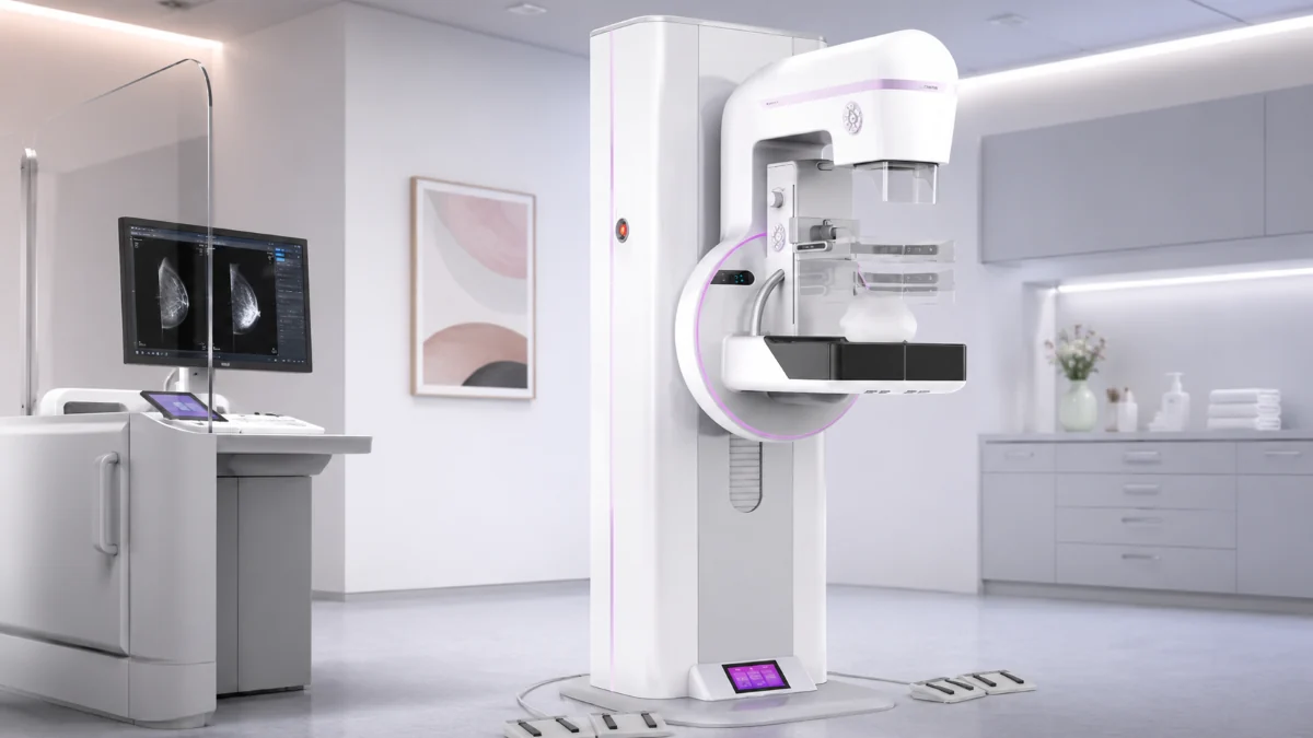
| Digital mammography | Fanghua Series | Intelligent motorized collimator, smart light field adjustment, AEC, optional tungsten target design | Links exposure control with precise coning and breast-imaging dose management |
At Angell, we connect AEC mode with the way each DR system is actually used in clinical work.
Our Changfeng Series uses a proprietary 47-inch large-format detector to enable full-spine and full-lower-limb imaging in a single exposure. The system also comes standard with AEC and intelligent automatic collimation. The detector provides the required coverage for long-length examinations, while AEC and collimation support exposure termination and radiation field control during image acquisition.
Although the core principle of exposure feedback is shared across digital radiography, the parameters controlled by AEC may vary between general radiography and mammography.
In our Fanghua Series, AEC is combined with an intelligent motorized collimator and smart light-field adjustment for precise coning. An optional tungsten-target design is also available as part of the system’s dose-management configuration.
FAQ
What does AEC mode control in DR systems?
In general radiography, AEC mainly controls exposure termination. It affects exposure time and final mAs by measuring radiation reaching the sensing chamber or detector-side sensing area.
Does AEC mode reduce radiation dose?
AEC can support dose optimization, but its target is appropriate detector exposure, not minimum radiation. Final dose is affected by patient size, kVp selection, chamber choice, positioning, collimation, calibration, and EI/DI review.
Why can AEC cause overexposure if it is automatic?
AEC responds to the selected chamber. If that chamber is under dense anatomy, mediastinum, metal hardware, or contrast material, the signal may rise slowly, and exposure may continue longer before reaching the threshold.
When is manual exposure better than AEC?
Manual exposure may be more suitable for small extremities, trauma positioning, metal implants, bedside limitations, or pediatric cases where the active chamber cannot reliably represent the anatomy.
Conclusion
AEC mode in DR systems works by measuring transmitted radiation, converting that measurement into a control signal, and terminating exposure when the preset detector exposure target is reached. Its clinical value comes from more consistent detector exposure, reduced operator-dependent variation, and a more stable basis for repeat analysis and EI/DI review.
In our DR systems, we consider AEC as part of a complete exposure-control approach rather than an isolated automatic feature. Factors such as chamber selection, detector response, radiation attenuation, collimation, calibration, and operator training all influence how effectively AEC performs in clinical practice. Selecting the right exposure-control strategy also depends on the examination type, workflow requirements, and system configuration. For guidance on DR solutions and application-specific requirements, please contact us.
References
AAPM Report No. 116, An Exposure Indicator for Digital Radiography
AAPM Report No. 232 from Task Group 232