
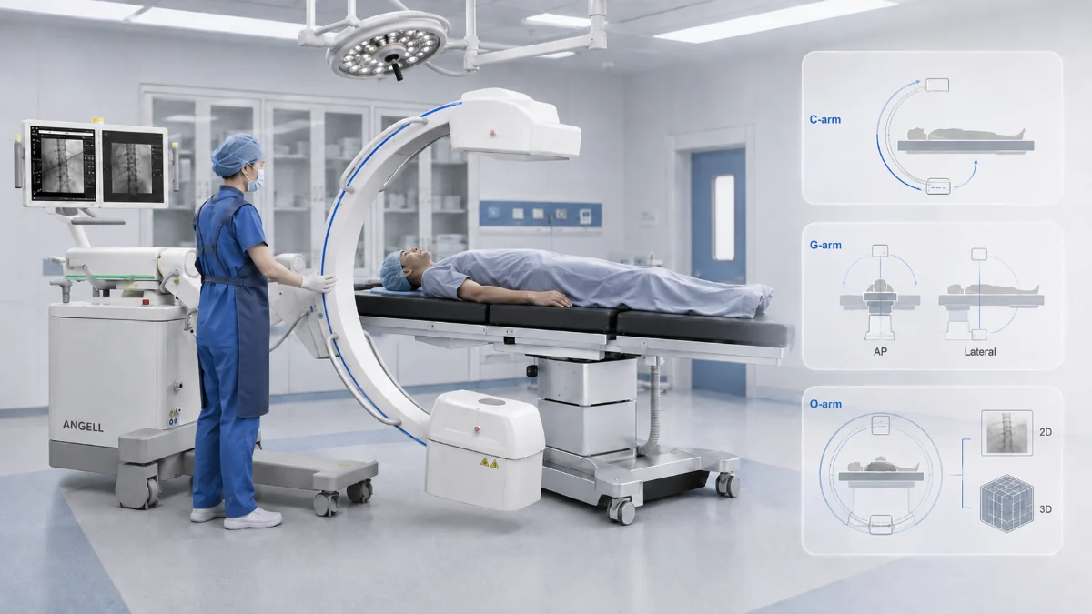
Operating rooms do not need every X-ray imaging system to solve the same problem. A trauma team checking implant position, a spine team preparing for navigation-related imaging, and a distributor matching equipment to a hospital's procedure mix may all ask about surgical X-ray systems, yet the workflow behind each request can be very different.
At Angell, our medical imaging team works with hospitals, distributors, and clinical partners to evaluate those workflows before selecting a system configuration. In real purchasing discussions, the device name is only the starting point; image output, projection geometry, room clearance, navigation needs, and dose-management requirements shape whether a mobile C-arm, a G-arm biplane workflow, or an O-arm-style 3D imaging system is the right direction.
The practical comparison begins inside the operating room: live 2D fluoroscopy, simultaneous AP/lateral views, and intraoperative 3D data. Pre- and post-operative imaging appears only where it helps separate surgical imaging from planning or follow-up workflows.
Choose by Imaging Workflow
| Imaging requirement | Appropriate starting point |
|---|---|
| Flexible live fluoroscopy around the operating table | Mobile C-arm |
| Simultaneous AP and lateral fluoroscopy | G-arm / biplane fluoroscopy |
| Intraoperative 2D/3D imaging linked to navigation | O-arm or verified 3D surgical imaging system |
Standing weight-bearing assessment belongs outside the operating room and is best evaluated as a planning or follow-up imaging workflow.
A mobile C-arm follows the procedure and provides live X-ray images as its imaging chain moves around the patient. In many surgical imaging discussions, a G-arm refers to a biplane system using two imaging chains arranged in perpendicular planes. The O-arm™ O2 imaging system is Medtronic’s mobile X-ray system for intraoperative 2D and 3D imaging and is compatible with certain image-guided surgery systems.
C-Arm, G-Arm, and O-Arm Are Not Three Versions of the Same System
A conventional mobile C-arm carries one X-ray source and one detector on opposite ends of a C-shaped arm. The system is wheeled to the table, and the arm is repositioned to obtain the required projection. Live fluoroscopy can show anatomy, guidewires, instruments, and implants while the procedure continues.
In clinical purchasing discussions, G-arm is best treated as shorthand for a mobile biplane fluoroscopy workflow. The underlying clinical idea is simultaneous biplanar fluoroscopy: keeping two orthogonal views available, commonly AP and lateral, so the surgical team does not have to rotate one C-arm between checks. Because this category is strongly tied to supplier terminology, buyers should confirm detector type, intended use, room clearance, and any 3D or navigation functions at the model level.
O-arm involves another imaging workflow. The O-arm O2 system is designed for 2D fluoroscopy and 3D imaging of structures such as bone and metallic objects, and is compatible with certain image-guided surgery systems. A fair comparison therefore has to consider imaging geometry, data type, and system integration together.
How Image Acquisition Changes During a Procedure
C-Arm: Repositioning One Imaging Chain Around the Patient
The source and detector maintain their relationship while the arm changes angle around the patient. This provides live observation without repeatedly moving the patient. When AP and lateral images are both required, the operator adjusts the same imaging chain between views.
G-Arm: Simultaneous AP and Lateral Fluoroscopy
In current supplier examples, a G-arm is marketed around two orthogonal imaging chains that provide AP and lateral views during the same procedural workflow. Both planes remain available during the procedure, which suits work where instrument direction requires continuous checks from the front and side. 3D capability varies by model and must be verified at the intended-use level.
O-Arm: Intraoperative 2D and 3D Image Acquisition
The O-arm supports 2D fluoroscopy and 3D acquisition in the surgical environment. A 3D scan collects projections around the patient and reconstructs volumetric data for intraoperative review and, with compatible systems, navigation. This sequence differs from continuous fluoroscopy and is not live 3D video.
Important Exception: Some C-Arms Can Also Provide 3D Imaging
The category boundary is more nuanced than equating C-arm with 2D and O-arm with 3D. Some mobile C-arms are designed for both 2D and 3D intraoperative imaging; one commercially available system, for example, is described by its manufacturer as a mobile 2D/3D C-arm with navigation data transfer capability. Buyers should confirm the acquisition mode, reconstructed volume, navigation interface, and approved use for each model.
Side-by-Side Comparison: C-Arm vs. G-Arm vs. O-Arm
| C-Arm | G-Arm | O-Arm | |
|---|---|---|---|
| Typical output | Live fluoroscopy and still 2D images; selected models add 3D | Simultaneous AP and lateral fluoroscopy | Intraoperative 2D fluoroscopy and 3D imaging |
| Projection change | One imaging chain is repositioned | Two planes remain available | Gantry supports 2D positioning and 3D acquisition |
| Navigation | Model-specific | Model-specific | Compatible with specified image-guided systems |
| Main strength | Mobility and flexible projection control | Continuous orthogonal viewing | Volumetric imaging and navigation-related workflow |
| Room planning | Arm depth, detector clearance, workstation | Dual-plane clearance and staff access | Gantry path, table compatibility, navigation equipment, storage |
| Limitation | Repositioning between orthogonal views | Specialized geometry and workflow | More installation and integration requirements |
These are category-level distinctions. The technical data sheet, intended-use documentation, and local regulatory status remain essential for the exact configuration.
Clinical Workflow Fit: Which System Matches Which Procedure?
Routine orthopedics, fracture reduction, and implant checks — mobile C-arm fluoroscopy provides repeated checks of alignment, instrument direction, and implant position.In orthopedic and trauma-related checks, our C-arm workflow focuses on implant-position adjustment under fluoroscopy and internal-fixation review after movement or joint activity, where the team needs to judge whether an implant may shift under motion. A G-arm becomes relevant when simultaneous AP and lateral views are central to the procedure. Volumetric imaging deserves consideration when cross-sectional information or navigation-ready data is needed during the case.
Spine procedures requiring biplanar views or navigation— continuous orthogonal viewing points toward biplane fluoroscopy. In PKP-type workflows, C-arm fluoroscopy is used to localize the affected vertebra and guide the puncture route through the pedicle; the practical image-quality question is whether the pedicle boundary can be seen clearly enough for needle-path confirmation. When the plan requires volumetric data or navigation integration, evaluation shifts toward an O-arm or a verified 3D C-arm.
Vascular, urology, pain management, and trauma workflows — mobile fluoroscopy is practical when the team needs to follow a guidewire, catheter, needle, access path, stone, stent, fracture line, or implant position in real time. For these cases, the purchase decision should focus on table access, movement route, repeated fluoroscopy checks, and dose-management tools rather than 3D capability alone. Our C-arm workflow materials also emphasize implant-position adjustment under fluoroscopy and internal-fixation review after movement or joint activity, which keeps the evaluation tied to live surgical decision-making.
Radiation and Dose Management
Radiation exposure is not decided by the arm shape alone. A mobile C-arm case may involve many short fluoroscopy checks as the arm is repositioned around the table. A G-arm workflow may reduce repeated movement when AP and lateral views are needed together, but each imaging plane still needs clear exposure control. An O-arm or verified 3D C-arm adds a different question: how many 3D acquisitions are required during the case, and under which protocol?
The FDA notes that fluoroscopy dose varies by procedure and should be kept to the lowest acceptable exposure for the shortest necessary time. For procurement, that means buyers should compare dose by clinical scenario rather than by product category name. A practical review should include fluoroscopy time, pulse or frame rate, field size, repeat imaging, DAP display, reference air kerma where applicable, low-dose modes, staff shielding, and operator position.
Dose-management features also need careful wording. Auto exposure, brightness stabilization, dose display, collimation, and remote exposure can help teams manage imaging behavior. A claimed percentage reduction, however, should only be used when the manufacturer provides a defined comparison method, test condition, and supporting evidence.
Detector and Image Quality: Flat-Panel C-Arm vs. Image Intensifier C-Arm
Within the C-arm category, detector architecture changes image geometry and tableside access. A flat-panel detector (FPD) uses a flat digital sensor, producing a rectangular field without the pincushion and magnetic-field-related distortion associated with a curved image-intensifier input surface. It can provide a more uniform field response toward the edges, depending on detector design and imaging protocol. Because FPDs do not rely on an intensifier tube, they avoid the image-intensifier tube aging mechanism that can affect long-term image stability and dose management. The slimmer detector housing leaves more physical room around the patient and table.
These architectural differences describe the detector design, not a guaranteed improvement in every image-quality or dose parameter. Field of view, generator design, imaging protocols, processing software, and calibration procedures remain specific to each system.
Where a Mobile Dynamic FPD C-Arm Fits
When the required workflow is flexible live fluoroscopy around the operating table, a mobile dynamic FPD C-arm becomes the more relevant category to evaluate. This is where our HUA II Series fits into the comparison.
The main value is not only image capture. In a real operating room, the team also has to consider where the workstation is located, how the C-arm moves around the table, and whether the setup can adapt as the room layout changes. HUA II can convert between all-in-one and split configurations, which makes it useful for surgical teams that need different equipment arrangements across procedure rooms.
For intraoperative use, its dynamic FPD is intended to support fluoroscopic observation during implant-position adjustment and post-operative assessment. Dose-management features such as auto exposure, APR, laser positioning, ABS with IDC, DAP display and analytics, and remote exposure matter because they help the team control imaging behavior during repeated checks.
This is also where the comparison with O-arm needs discipline. HUA II is for mobile dynamic FPD fluoroscopy workflows: repeated live checks, implant-position adjustment, and post-operative assessment under fluoroscopy. It should not be treated as an O-arm-style system for intraoperative 3D volume acquisition or navigation-related imaging. When the surgical plan requires 3D data during the case, the evaluation should move toward an O-arm or a verified 3D C-arm.
Operating-Room Fit: Clearance, Movement, and Integration
For a C-arm, we review field of view, arm depth, patient clearance, table height, approach angle, and workstation location. A detector may cover the anatomy yet create poor access when the arm cannot reach the required projection inside the room. Our mobile C-arm guidance specifically identifies detector field of view, arm depth, free space, common procedures, and dose-management features as core selection factors.
A G-arm adds another imaging chain, so both planes need to be mapped against the table, accessories, sterile field, anesthesia equipment, and staff positions. An O-arm assessment extends to gantry travel, table compatibility, 3D acquisition clearance, navigation integration, power, storage, and emergency patient access. Installation drawings and a room simulation provide stronger evidence than brochure photographs.
Related Planning and Diagnostic Imaging Outside the OR
Weight-bearing 3D and fixed-room dynamic DR may appear in the same procurement discussion, but they should not be treated as direct substitutes for C-arm, G-arm, or O-arm systems in the operating room.
Our WR-3D supports standing, weight-bearing 3D assessment for the full spine, full lower limbs, hip, knee, and ankle, with MIP, MPR, VR reconstruction, and AI-assisted orthopedic measurements. A 2025 CRMC report on Cotabato Regional and Medical Center’s WR-3D installation illustrates this outside-OR role: the reported workflow included weight-bearing MPR, full-spine and full-leg imaging, and AI-supported Cobb angle and vertebral rotation measurements. These functions support diagnosis, planning, and follow-up rather than intraoperative navigation.
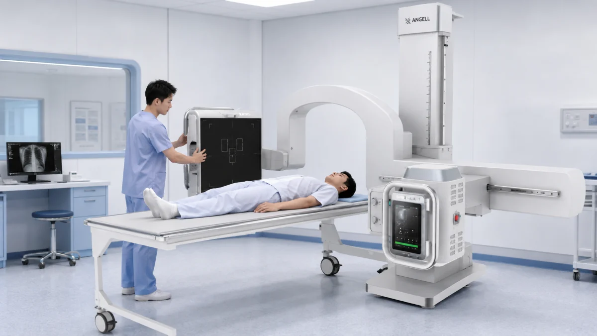
Our DTP580 Series is a Multifunctional UC-ARM Dynamic DR System for fixed diagnostic-room use. Its rotating detector and horizontal arm help technologists handle specialized projections such as Waters view, patella axial view, calcaneal axial view, and cross-table lateral view. It also supports radiography, fluoroscopy, contrast-enhanced imaging, full-body stitching, and pneumoconiosis examination.
The boundary matters: WR-3D and DTP580 support planning, diagnostic review, and follow-up workflows outside the OR, while C-arm, G-arm, O-arm, and verified 3D C-arm systems are selected for imaging decisions made during surgery.
Selection Matrix for Hospitals and Distributors
| Primary need | System category to evaluate |
|---|---|
| Flexible imaging during surgery | Mobile dynamic FPD C-arm |
| Simultaneous AP and lateral views during surgery | G-arm / biplane fluoroscopy |
| Intraoperative 3D data and navigation-related use | O-arm or verified 3D C-arm |
| Outside the OR: standing loaded orthopedic assessment | Weight-bearing 3D |
| Outside the OR: multi-position diagnostic radiography and fluoroscopy | UC-ARM Dynamic DR System |
Before requesting a quotation, document the procedure mix, required output, case volume, room dimensions, table type, movement route, dose-reporting needs, existing navigation platform, local registration requirements, and service coverage.
Conclusion
C-arm selection starts with flexible live fluoroscopy. G-arm selection begins with a genuine need for simultaneous AP and lateral views. O-arm evaluation centers on intraoperative 3D data and navigation integration. Match the system to the surgical decision that must happen inside the operating room; the rest of the evaluation becomes easier to structure.
If your team is comparing intraoperative C-arm, G-arm, O-arm, or verified 3D C-arm workflows, our Angell imaging team can help review your procedure requirements, room layout, detector configuration, dose-management needs, and navigation-related requirements before selecting a system.
References
Medtronic O-arm surgical imaging system