
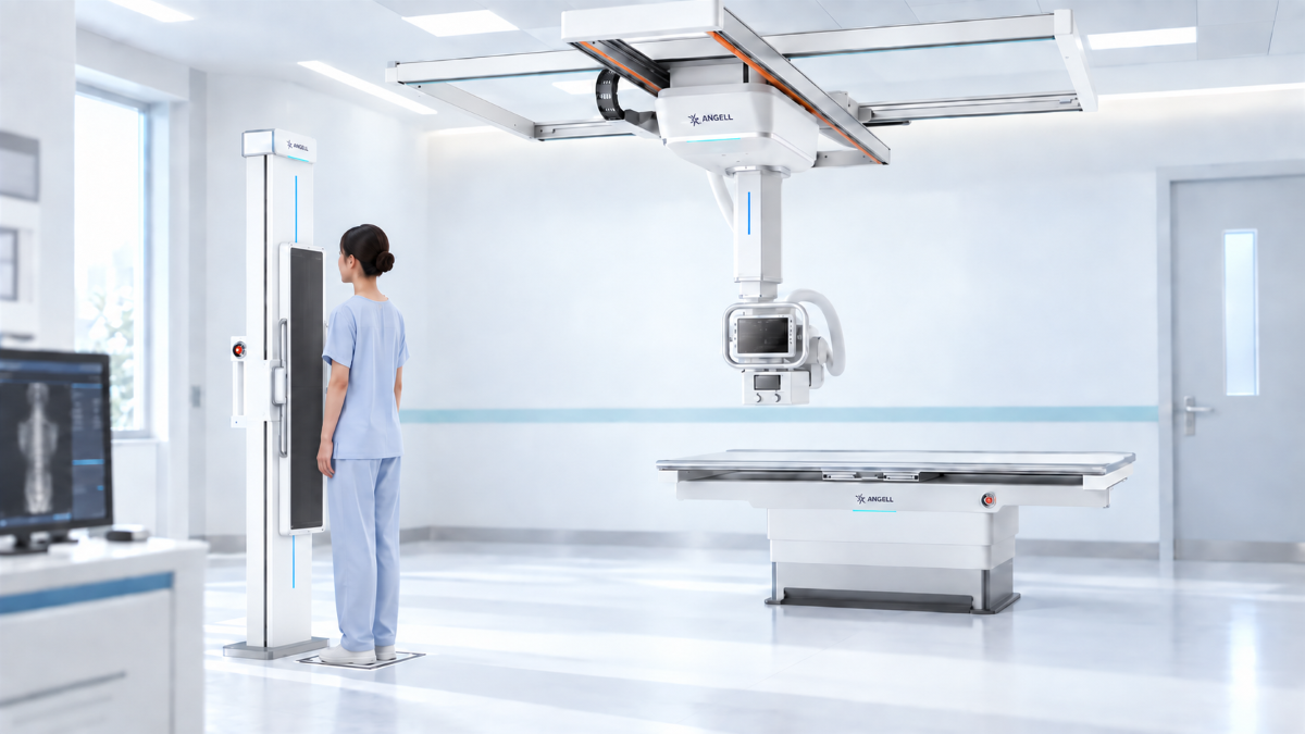
For adolescent idiopathic scoliosis (AIS), we start with two questions: does the department need dependable full-length 2D views, and does the clinical team also need three-dimensional information in a standing position? Image stitching and single-exposure full-frame imaging address the first question. Weight-bearing volumetric imaging addresses the second. A longer radiograph does not become a 3D scan, and acquiring 3D data does not automatically make every follow-up examination more useful.
The selection starts with the required output: comparable projections for curve follow-up, a continuous long-length radiograph without sequential joins, or reconstructed planes for reviewing anatomy in 3D. Detector size alone cannot settle that choice. Ask what the clinician must read, what positioning the patient can sustain, and how future examinations will be compared.
Comparing the Three Imaging Workflows
Here, weight-bearing 3D means a standing volumetric acquisition. Paired biplanar radiographs can support 3D skeletal modeling when the appropriate modeling workflow is used; that model is not a scrollable reconstructed volume.
| Comparison point | Multi-exposure stitching | Single-exposure full-frame | Weight-bearing volumetric 3D |
|---|---|---|---|
| Data output | A composite 2D radiograph | A long-length 2D projection | A reconstructed 3D volume |
| Acquisition pattern | Overlapping exposures acquired sequentially | One exposure for each projection | Multiple projections acquired during rotation |
| Motion concern | Movement between exposures can affect alignment | Movement during the exposure can still blur the image | Movement during rotation can affect reconstruction |
| Stitching requirement | Source images are joined | No sequential-image stitching within the captured field | Extended coverage may involve joining scanned volumes |
| Main information gained | Full-length projected anatomy | Continuous projected anatomy without sequential joins | Anatomy reviewed across reconstructed planes while weight-bearing |
| Department starting point | General imaging with full-spine examinations | Frequent long-length orthopedic imaging | Selected assessments requiring standing volumetric information |
The distinction lies in how the anatomy is covered and what type of data is produced. Standing positioning is available in both 2D and 3D workflows; it is not exclusive to volumetric imaging.
How Multi-Exposure Stitching Fits a Shared DR Room
When the required anatomy extends beyond one detector field, stitching combines overlapping acquisitions into a full-length radiograph. The images must align well enough to preserve the anatomical relationships used for measurement. It is a way to extend coverage, not a change from 2D to 3D.
Our DTP580 Series brings full-body stitching into a multifunctional UC-ARM Dynamic DR system alongside radiography, fluoroscopy, and contrast-enhanced imaging. For a department balancing scoliosis referrals with other examinations, the attraction is the breadth of work the room can handle.
Join quality matters. Posture changes between exposures can complicate alignment, and merging errors can mimic anatomical abnormalities. A 2023 JBJS Case Connector report traced an apparent L4 compression fracture on a postoperative stitched lateral image to a merging error; focused lumbar views showed a normal vertebra. The patient had Marfan-associated scoliosis, not AIS, so this is a join-quality example rather than AIS outcome evidence.
In a stitching workflow, source-image review should come before reliance on the composite measurement. Inspect suspicious overlap regions and ask, during an equipment demonstration, how the original frames and joins can be reviewed. A polished panoramic image alone cannot show how a technologist would investigate a questionable merge. The 2023 case authors also recommended labeling stitched images and indicating overlap regions; ask whether the proposed workflow makes those joins clear to the reader.
What Single-Exposure Full-Frame Imaging Changes
Full-frame imaging removes the need to assemble sequential exposures within the covered field. Our Changfeng Series uses a proprietary 47-inch large-format detector for single-exposure full-spine and full-lower-limb imaging. AEC and intelligent automatic collimation are standard.
The practical gain is continuity of acquisition. The upper and lower portions of the image come from the same exposure, so a postural adjustment between separate shots cannot create a mismatch at a join. The patient still needs to remain still during exposure, and positioning still determines whether the required anatomy is included. Use representative patient sizes and both requested projections in the room trial; a large detector does not remove the need to verify actual field coverage.
One exposure also means one projection. A frontal and lateral examination requires separate views. Workflow comparisons should cover the complete requested examination, not one exposure against another system’s two-view study.
Our Changfeng platform also includes automatic angular stitching for recumbent full-body imaging, with bidirectional auto-tracking between the recumbent detector and tube head. Its large-format acquisition and recumbent stitching are separate capabilities. That matters when one room serves both standing scoliosis examinations and patients who need table-based positioning.
List standing full-length acquisition and recumbent angular stitching as separate protocols in the room specification. Include positioning and acquisition steps for each, so the team can evaluate the actual workflow rather than a feature label.
A continuous long radiograph remains a projection. Vertebral rotation can be estimated from projected landmarks such as the pedicles, but the image does not provide an axial cross-section to scroll through. That difference becomes important when the clinical request extends beyond full-length projected alignment.
What Weight-Bearing 3D Adds Beyond a Long Radiograph
Weight-bearing 3D becomes relevant when the team needs reconstructed planes of anatomy acquired while the patient stands. This changes the information available for assessment, not merely image length. Specify the additional views or measurements before deciding whether a volumetric examination is warranted.
Posture remains a separate part of that decision. Published standing-versus-supine AIS research found that both curvature and vertebral rotation changed with positioning. Reconstructing a supine examination in 3D does not recreate the geometry of a standing examination. Keep the acquired posture explicit whenever those images are compared. In a 3D equipment trial, watch how the technologist instructs the patient, confirms stance before rotation, and checks for weight shift or motion in the reconstructed series. Document that standing setup for later follow-up; “upright” alone is not a repeatable acquisition protocol.
EOS Biplanar Radiography vs. WR-3D Volumetric Reconstruction
EOS uses biplanar radiography to acquire paired X-ray projections. These images can be processed with the sterEOS workstation to create patient-specific 3D skeletal models and interactive measurement tools. This output is a modeled skeleton with associated parameters, not a reconstructed volume that can be reviewed slice by slice.
Our WR-3D uses volumetric imaging and provides coronal, sagittal, and axial reconstructions, with multiplanar reconstruction (MPR), maximum-intensity projection (MIP), and volume rendering (VR). We distinguish these approaches by what the reader can inspect: a skeletal model and its parameters, or reconstructed cross-sectional anatomy and volumetric views.
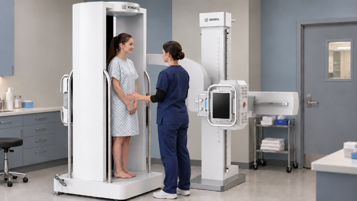
Both approaches derive 3D information from X-ray projections, but they do not produce the same data type. Compare the resulting views and measurements rather than relying on the label “3D” alone.
How WR-3D Extends Standing Volumetric Coverage
In WR-3D, the patient stands on a motorized rotating platform while the X-ray tube and flat-panel detector remain fixed. Each rotational acquisition collects projections that are reconstructed into a volume for cross-sectional review.
For extended longitudinal coverage, successive scan segments are registered and combined. This joins volumetric datasets, unlike the assembly of a conventional 2D panoramic radiograph. Weight-bearing 3D can therefore still involve stitching, but the stitched output retains volumetric information. Patient stability matters during rotation and between scan segments. The 2023 implementation study describes redundant margins and registration across segments to address intersegment mismatch. Request examples showing the extended-coverage join and ask which reconstructed segments remain available for review.
From Volumes to Scoliosis Measurements
WR-3D supports AI-assisted scoliosis measurement. Our technical materials mark this application as optional and list outputs such as Cobb angle, vertebral rotation, lumbar lordosis, and pelvic incidence. Confirm which modules are included in the proposed configuration, then trace each reported value to the selected anatomy, calculation method, and exported report during the demonstration.
At Cotabato Regional and Medical Center in the Philippines, our WR-3D installation was inaugurated in August 2025. That installation brings together standing MPR, full-spine imaging, and AI-supported Cobb angle and vertebral rotation measurements. It shows how we combine extended anatomical coverage with reconstructed planes and scoliosis-specific quantitative outputs within the same platform.
Can Cobb Angles Be Compared Across 2D and 3D Methods?
For adolescent idiopathic scoliosis follow-up, a newly reported angle does not necessarily mean the curve changed. Before introducing 3D measurements, establish how they relate to the existing 2D record and document any method transition.
Angell-affiliated coauthors participated in a 2024 study involving 53 patients with AIS and 88 spinal curves, alongside colleagues at West China Hospital and other institutions. The study compared conventional 2D measurements with three automatically calculated 3D methods. The Analytical Method and Plane Intersecting Method produced significantly larger angles than 2D measurements. The Plane Projection Method showed no statistically significant difference from 2D. That group-level finding does not establish that the methods are interchangeable for every patient.
Researchers segmented the study images with a 3D-UNet model and calculated the angles in 3D Slicer. Those research methods do not establish which algorithms are supplied in a current WR-3D software package; confirm the enabled method in the quote and demonstration. Further validation is needed, particularly for severe curves.
For follow-up, keep the acquisition position, selected end vertebrae, measurement plane, and calculation method visible in the record. When a method changes, document the transition explicitly. A 2D angle from one visit and a differently calculated 3D angle from the next should not silently appear as equivalent points on a progression chart.
In the software demonstration, trace a reported angle to its selected anatomy and calculation method, then verify comparison with prior examinations. Only after the output is defined can time and dose be compared on a like-for-like examination basis.
Compare Dose and Total Examination Time on the Same Basis
Compare dose for a defined imaging task: the same anatomical coverage, required views, representative patient size, and diagnostic image-quality target. Patient-size-specific settings matter especially in adolescent imaging; FDA guidance emphasizes adjusting technique to the patient and the clinical question.
Adjacent stitched exposures may contribute dose in overlapping regions. Removing those overlaps changes the acquisition, but does not by itself establish the total-dose difference between two examinations. Collimation, exposure settings, required views, and repeat acquisitions still need to be included. For a purchasing comparison, we would agree on an appropriate, consistent dose measure with the department’s medical physicist before comparing figures.
A 2023 validation study with 30 AIS volunteers evaluated an extended-coverage, weight-bearing cone-beam system and reported a CTDIvol of 1.23 mGy under its test protocol, alongside favorable image-quality assessments. That is a result for the tested system and protocol, not a universal dose figure for every WR-3D examination.
CTDIvol is a scanner-output index, not an individual patient dose. We use the study result to discuss the tested acquisition; a comparison with radiography needs a suitable common dose basis.
Total examination time needs the same discipline. Time patient positioning, every required acquisition, image checks, reconstruction, measurement, and transfer for reporting. Note where the technologist must intervene. A short exposure or fast calculation can coexist with a longer overall workflow. What matters to the department is how long it takes to produce the complete, reviewable examination.
These workflow categories are not always tied to separate rooms. At CMEF 2026, we announced Nirvana as a platform combining a 120 cm full-frame dynamic flat-panel detector with standing weight-bearing 3D. For procurement, confirm local availability, regulatory status, included acquisition protocols, and enabled measurement software in the proposed configuration.
Matching the Imaging Method to the Department
A mixed-use DR service and a spine-focused department face different equipment decisions. More scoliosis referrals raise a throughput question; a request for cross-sectional anatomy changes the data the team must receive.
| Department need | Workflow we would evaluate | Decisive demonstration |
|---|---|---|
| Full-spine studies within a mixed radiography service | Multifunctional DR with stitching, including our DTP580 Series | Required coverage, source-image access, and transitions between examinations |
| Frequent standing full-spine and long-limb projections | Single-exposure full-frame imaging with our Changfeng Series | Both requested projections, anatomical coverage, and the complete positioning sequence |
| Standing cross-sectional or volumetric assessment | Our WR-3D weight-bearing volumetric workflow | Reconstructed planes, extended-coverage joins, and required measurement outputs |
Image handoff deserves its own test. For 2D, show how the complete projection and measurements reach the reading workstation. For 3D, request reconstructed series and the measurement report. Our WR-3D technical materials list PACS upload of VR images, 3D segmented-model images, MPR reconstructions, and measurement reports as optional. Confirm the quoted configuration, then test both the requested PACS/DICOM transfer and how each required output appears on the receiving workstation.
Before acceptance, request the current DICOM Conformance Statement and map each required output to the receiving system: original 2D frames, stitched composites, reconstructed series, and measurement reports. A successful send is not enough; verify that each required object opens, is correctly identified, and can be compared at the reporting workstation.
WR-3D also offers conventional 2D radiography and stitching, fluoroscopy, and contrast-study workflows alongside weight-bearing 3D. Conventional stitching produces a 2D composite; extended volumetric coverage joins reconstructed scan segments instead. Demonstrate the protocols separately and include mode transitions in the room schedule.
For an existing service, start with representative examination requests and the current reporting process. A new spine program should begin with required views and measurements. Both routes convert a feature list into a room specification tied to actual work.
Frequently Asked Questions
Is a standing full-spine X-ray the same as a 3D scan?
No. “Standing” describes patient position, “full-spine” describes coverage, and “3D” describes reconstructed information. A standing full-length radiograph is still a 2D projection.
Does a single full-frame exposure include frontal and lateral views?
No. Each exposure produces one projection. Count both acquisitions whenever frontal and lateral views are required.
Is full-frame imaging always lower dose than stitching?
Not necessarily. Exposure count alone cannot establish a dose ranking. Compare the full protocol, including patient size, field coverage, required views, exposure settings, and repeats.
Why retain standing positioning when moving from 2D to 3D?
Patient position can change measured spinal alignment. When the question concerns anatomy under standing load, upright 3D acquisition preserves that examination context. Document the measurement method as well, so a change in technique is not mistaken for a change in the curve.
Choose the Workflow Around the Required Result
The specification starts with the image and measurement the clinical team needs. Stitching extends 2D coverage, full-frame acquisition removes sequential joins, and weight-bearing volumetric imaging adds reconstructed spatial information. The right choice is the one that delivers the required result within the department’s actual workload.
Planning a full-spine imaging service or upgrading an existing room? Contact us with three starting inputs: expected examination volume, required standing and recumbent views, and the 2D or 3D measurements clinicians need. For a configuration proposal, add the patient age and size range, room dimensions, PACS/DICOM requirements, and installation country. We can then scope the acquisition workflow, measurement software, and installation needs for your team’s evaluation.