
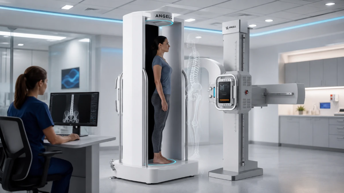
A radiographic 3D imaging system is an X-ray-based platform that captures multiple projections of the body and turns them into three-dimensional anatomical information. Depending on the system design, the output may be a true volumetric dataset or a calibrated 3D skeletal model. In orthopedic imaging, the strongest use case is often the ability to separate overlapping bone structures, review coronal, axial, and sagittal views, and measure spatial relationships that a single flat radiograph cannot show.
Orthopedics is one of the clearest clinical use cases, especially when the question depends on standing, weight-bearing assessment of the spine or lower limbs. Under gravity, a patient’s posture can change how bones align, how joints load, and how a surgeon plans correction. That load-dependent information may be reduced or altered in supine CT or MRI. WR-3D illustrates this category through standing cone-beam acquisition, full-spine and lower-limb coverage, AI-assisted measurement, and orthopedic planning workflows outside the operating room.
What Type of 3D Data Does Radiographic Imaging Produce?
For orthopedic imaging teams, “3D” is less a marketing label than a question of data type and clinical use case.
CT and MRI produce volumetric datasets, but usually with the patient supine. Biplanar X-ray systems use calibrated radiographs and modeling algorithms to generate patient-specific 3D skeletal surface models. Intraoperative systems such as O-arm create volume data for surgical workflows inside the operating room. Standing cone-beam CT captures weight-bearing 3D volumes outside the operating room, with the patient upright under physiological load.
For radiology and orthopedic teams, the practical question is which data type the workflow requires.
How Standing Cone-Beam Radiographic 3D Imaging Works
A weight-bearing 3D system is built differently from conventional CT. Instead of moving a patient through a rotating gantry, a standing cone-beam system keeps the X-ray tube and flat-panel detector fixed while the patient stands on a motorized rotating platform.
WR-3D follows this architecture: fixed tube, fixed flat-panel detector, cone-beam acquisition, and patient rotation on a standing platform. One rotation captures projection data for the selected region and reconstructs coronal, axial, and sagittal views, plus MIP, MPR, and VR outputs. The same platform also supports 2D radiography, stitching, fluoroscopy, and contrast workflows, so departments do not have to treat standing 3D imaging as a separate island.
For full-spine or full-lower-limb coverage, WR-3D performs sequential upright scans along the vertical axis and stitches the reconstructed volumes. Its 350 mm cross-sectional field of view and up to 1,450 mm Z-axis coverage enable full-spine or full-lower-limb review in one examination session.
That coverage supports full-spine scoliosis assessment and full-leg mechanical-axis evaluation in one continuous, weight-bearing dataset.
Why Standing Position Changes the Clinical Picture
Gravity changes skeletal relationships. In standing posture, spinal compression, pelvic orientation, joint-space width, and lower-limb mechanical axis may differ from supine imaging. This is why load-dependent information can be reduced or altered when the patient lies down for CT or MRI.
A standing-versus-supine scoliosis study quantified the difference: scoliotic curves measured an average Cobb angle of 55.72° on standing radiographs versus 39.42° on supine images, a spontaneous correction of 29.78% associated with position change. That gap can be clinically meaningful. The Scoliosis Research Society describes observation for curves less than 25° to 30°, bracing for growing patients with curves larger than 25° but smaller than 45° to 50°, and surgery usually for curves greater than 45° or 50° or at high risk of progression.
Below the waist, weight-bearing imaging can reveal hip-knee-ankle malalignment, loaded joint-space narrowing, and femoral or tibial torsion in a 3D volume. Those findings matter for workflows such as high tibial osteotomy planning, knee osteoarthritis review, and deformity follow-up.
That functional picture is central to correction planning, and scoliosis offers one of the clearest examples because treatment decisions still rely on measurable alignment values. The Cobb angle therefore becomes a useful place to show how 3D radiographic data can add information beyond a flat standing X-ray.
Cobb Angle Measurement: A High-Intent Use Case
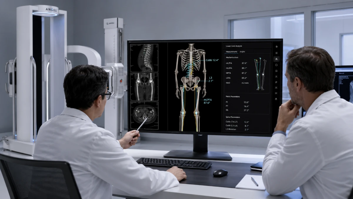
The Cobb angle guides AIS management, from observation and bracing to surgical referral. It is also a high-intent search topic because clinicians, patients, and families need to understand what the number means.
Traditionally, clinicians measure Cobb angle on a standing anteroposterior X-ray by selecting the most-tilted vertebrae at the top and bottom of the curve and measuring the angle between their endplate lines. The method remains central to scoliosis management.
The limitation is dimensional: scoliosis is three-dimensional, while a flat X-ray is a single projection. Vertebral rotation cannot be precisely measured from a 2D image, and the apparent Cobb angle can shift with positioning and projection angle.
A 2024 The Spine Journal study evaluated this gap directly. It analyzed 53 AIS patients and 88 spinal curves, comparing conventional 2D Cobb angle measurements with automatic 3D measurements from WR3D imaging. AM and PIM produced larger values than 2D measurement, while PPM showed no statistical difference from 2D. In WR-3D demonstration materials, one 2D-versus-3D Cobb example shows 55.2° versus 73.6°, a difference of 18.4°; that example is useful as a case illustration, not a universal expected gap.
The 3D dataset also adds vertebra-by-vertebra rotation values. That differs from 2D Nash-Moe grading, which gives categorical rotation estimates, and may inform rod contouring, screw trajectory planning, and surgical simulation.
3D measurement therefore does not replace the traditional Cobb angle; it adds rotation, sagittal alignment, and true spatial curvature around it.
What Clinicians Can View, Measure, and Report
Cobb angle is one example of a wider measurement workflow. The practical value of WR-3D is easiest to see in three outputs:
Coverage areas. WR-3D supports standing 3D assessment of the full spine, full lower limbs, hip, knee, and ankle, allowing clinicians to review alignment across the anatomical chain instead of separating every region into isolated scans.
Visualization. Reconstructed volumes can be reviewed as MPR slices, MIP projections, or 3D volume-rendered models. Optional PACS upload of MPR images, 3D/VR images, and measurement reports helps keep 3D review inside the department workflow.
AI-assisted measurement. WR-3D offers optional automatic measurement packages for the full spine, full lower limbs, hip, knee, and ankle. The full-spine package covers 20 spine and pelvis parameters, while the full-lower-limb package covers 77 lower-limb and pelvis parameters, including mechanical axis, HKA, JLCA, TFA, LDFA, and MPTA. For lower-limb assessment, the workflow can also build independent coordinate systems for each limb, supporting asymmetric deformity and postoperative alignment review. Our automatic measurement workflow describes a one-click structured report generated in about 15 seconds; WR-3D materials also describe full spine or lower-limb examination-plus-report workflows of about 15 minutes.
Application-specific outputs. For knee assessment, WR-3D workflows can include joint-space measurement, JLCA, joint-gap heat maps, and intercondylar notch metrics. For foot and ankle work, documented parameters include Pitch, Meary, Böhler, Preiser, and Langré angles. Optional STL export can support 3D printing for brace design, surgical guides, clinical education, and pre-/post-intervention comparison.
Radiographic 3D vs. 2D DR, CT, MRI, and Intraoperative 3D Imaging
Once those outputs are clear, the next question is how weight-bearing 3D fits beside the systems a hospital already uses. Hospitals usually layer these modalities; the key question is what gap weight-bearing 3D imaging fills inside the department’s imaging toolkit.
| 2D Digital Radiography | CT (Supine) | MRI (Supine) | Intraoperative 3D (O-arm / 3D C-arm) | Weight-Bearing Cone-Beam 3D | |
|---|---|---|---|---|---|
| Patient position | Standing or supine | Supine | Supine | Supine (on surgical table) | Standing, weight-bearing |
| Data type | Single-plane projection | Volumetric cross-sections | Volumetric, soft-tissue contrast | Volumetric, bone and metal | Volumetric, bone under load |
| Strengths | Fast, widely available, low cost | High spatial resolution for bone and cross-sectional localization | Superior soft-tissue detail, no radiation | Real-time surgical guidance, navigation-compatible | Load-dependent alignment, full-chain review, lower reported dose in validated WR-3D spine protocols |
| Limitations | Overlapping structures, no depth data | No weight-bearing data, higher dose | No weight-bearing data; less suitable than CT for fine cortical bone detail | Limited to OR use, no weight-bearing | Bone-focused, no soft-tissue contrast |
| Radiation dose | Very low (single exposure) | Moderate to high | None | Moderate (per acquisition) | Protocol-dependent; WR-3D spine validation reported ~1.23 mGy CTDIvol |
| Best fit | Screening, follow-up, quick checks | Detailed anatomy, surgical planning | Disc, ligament, nerve assessment | Screw placement verification, intraoperative navigation | Pre-op alignment planning, post-op follow-up, scoliosis assessment |
The dose comparison should stay protocol-specific. A 2023 validation study on large-coverage weight-bearing cone-beam CT reported 1.23 mGy CTDIvol, 0.6% low-contrast resolution at 4 mm, and 8 lp/cm spatial resolution for whole-spine WR-3D imaging. A WR-3D protocol comparison pairs that result with a selected spiral CT lumbar protocol listed at 13.2 mGy CTDIvol. This supports an “about one-tenth under these protocol assumptions” statement, not a universal dose ratio.
Weight-bearing cone-beam 3D complements CT and MRI by adding functional, bone-focused data under load. For soft-tissue pathology such as disc herniation, ligament injury, or tumor margins, CT or MRI remain the appropriate modalities.
The C-Arm vs. G-Arm vs. O-Arm guide covers intraoperative imaging. In short, C-arm, G-arm, and O-arm systems support decisions during surgery, while weight-bearing 3D systems support diagnosis, planning, and follow-up outside the operating room.
When Should a Hospital Consider a Weight-Bearing 3D System?
A hospital should consider weight-bearing 3D imaging when load-dependent skeletal alignment is a frequent clinical question, not an occasional edge case. The strongest fit is a department that regularly manages scoliosis, lower-limb deformity, knee osteoarthritis, or postoperative alignment follow-up.
Clinical demand. Prioritize departments where standing alignment changes the decision, such as scoliosis treatment planning, HTO planning, knee OA staging, or deformity follow-up.
Data requirements. If the question is mechanical axis, loaded joint space, standing spinal balance, or torsion, supine CT can leave a gap. If the question is soft tissue, CT or MRI should lead.
Volumetric vs. modeled 3D. Biplanar systems can create patient-specific skeletal surface models from calibrated two-plane radiographs. Cone-beam systems provide voxel-based volumes for cross-sectional review and volume rendering. The choice depends on whether the workflow needs a surface model, a full volume, or both.
Workflow efficiency. Manual 2D measurement is time-consuming and operator-dependent. WR-3D’s automated measurement workflow can standardize landmark detection and reporting, with documented full spine or lower-limb examination-plus-report workflows of about 15 minutes.
Integration. PACS/DICOM output, measurement reports, and 3D-printing-ready files determine whether the system fits the existing workflow or creates a separate data path.
Room and installation. Site planning should confirm room space, rotating-platform clearance, and radiation shielding before procurement.
From Imaging to Orthopedic Planning
After clinical fit and installation requirements are defined, the next strategic question is how far the system can support planning beyond image capture. For WR-3D, that direction is a tighter link between imaging data and orthopedic planning.
In the 2026 Global Spine Congress report from Istanbul, WR-3D capabilities include 3D pedicle screw trajectory planning, correction-strategy simulation, biomechanical evaluation, and patient-specific 3D-printed surgical guides. The same report states that the system had entered clinical routine at three hospitals in Istanbul for scoliosis assessment, postoperative comparison, and standing-state parameter measurement.
This connection between standing imaging, automated measurement, surgical simulation, and patient-specific outputs is where WR-3D becomes more than a scanner; it becomes part of the orthopedic planning workflow.
FAQs
Is a radiographic 3D imaging system the same as CT?
Not exactly. Both can reconstruct cross-sectional images from X-ray projections, but conventional CT usually scans a supine patient, while a weight-bearing cone-beam system scans the skeleton under load. In the WR-3D validation data and protocol comparison above, the reported spine dose is lower than the selected spiral CT protocol, but the ratio is protocol-dependent.
Do digital X-rays produce 3D images?
Standard DR produces two-dimensional projection images. WR-3D combines 2D radiography with cone-beam 3D scanning, stitching, fluoroscopy, and contrast workflows, but a routine chest or hand X-ray remains flat unless a dedicated 3D acquisition workflow is used.
Why is standing position important in orthopedic imaging?
Standing position loads the spine and joints, changing pelvic orientation, joint space, and alignment. Supine imaging removes those forces, so load-dependent deformity or joint-space narrowing may be underestimated or altered.
Can weight-bearing 3D imaging replace CT or MRI?
No. Weight-bearing 3D imaging is optimized for skeletal alignment under load. It cannot replace MRI for soft-tissue contrast or high-resolution CT when CT-level anatomical detail is required.
Conclusion
A radiographic 3D imaging system adds dimensional context that flat X-rays cannot provide. In spine and lower-limb orthopedics, its strongest value appears when the clinical question is alignment under gravity: scoliosis assessment, deformity correction planning, knee osteoarthritis review, or postoperative follow-up. WR-3D brings that value into a standing cone-beam workflow with AI-assisted measurement, full-chain review, and planning outputs that support orthopedic decision-making. To discuss whether WR-3D fits your department’s imaging workflow, contact us.